Essential parts which are used in weft insertion motion of the loom:-
Essential parts which are used in weft insertion motion of the loom:-


 Image of Pre-winder.

 image of balloon breaker.
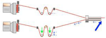 Image of weft break system.
 image of tandem nozzle,
 Image of main nozzle.
 image of sub nozzle.
 image of arrangement of sub nozzle.
 Image of H-1 feeler.
 Image of The distance between H-1 & H-2 feeler is 125 mm.
WEFT INSERTION MOTION:-
The movement of the yarn inserted in weft passage is a complex motion. It is called weft insertion motion of loom , it is not a positively controlled process.
Fig. of A weft insertion motion of loom.
Here are the some following parts which are used in weft insertion motion of the loom.
1. Plate spring tenser.
2. L H sensor.
3. Pre-winder.
4. Electromagnetic pin.
5. Balloon sensor.
6. Balloon breaker.
7. ABS / WBS.
8. Tandem nozzle.
9. Electrical cutter.
10. Sub nozzle.
11. H-1 feeler.
12. H-2 feeler.
(1) PLATE SPRING TENSER:-
Image of plate tenser
Here,
1.Plate spring tenser
2. Plate spring.
3. Adjusting nut.
(2) L H SENSOR:-
This L H sensor detect the presence of or absence of weft yarn at the preset timing . If it detects a weft yarn, the machine continues to running, no weft yarn , the machine stop.
Fig of L H sensor.
(3) Pre-winder:-
Adjust the drum height 1&2 at an equal distance from the horizontal center-line assumed between tandem nozzles. Drum heads 1&2 , so that it’s center of tandem nozzles. Drum should be tilted down 14 degree from a horizontal position.
Right to left position the electric drum unit so that the distance from balloon cover the tandem nozzle comes to 50 mm. The distance from electromagnet pin to the tandem nozzle should be 400–420 mm.
Adjust drum head 1&2 to front or rear so that it’s center line passes the center of the tandem nozzle and main nozzle. Adjust the height of chesses tensor and eyelet front to rear positioning. By using push button feed a weft yarn into the drum. Yarn feeding air is supplied from main tank.
Name of the components:-
1. Winding sensor.
2. Electromagnetic pin.
3. Measuring band.
4. Cover.
5. Motor.
6. In let piece.
7. Winding arm.
8. Push button.
9. Adjust bracket.
(4) Electromagnetic pin:-
This pin measures the length of a weft yar for one pick. Make the clearance between this pin and measuring band 0.5 to 0.8 mm.
Image of electromagnetic pin
(5) Balloon sensor:-
This sensor detects the number of weft winding on measuring band and the first turn , second (n-1)th turns and nth turn. Adjust the clearance between the sensor and the measuring band 0.5 to 1.2 mm.
Measuring length= Drawing in width+ weight in selvedge in length.
(6) Balloon breaker:-
The balloon breaker makes the filling balloon small to reduce release tension and filling insertion resistance. It is required to operate the loom stability with weak filling.
It controls the balloon size and pressure of the main nozzle. It guides the weft threads.
(7) Weft break system:-
WBS, weft break system prevents broken picks and slackpicks.
Breaking force is applied to the filling just before the insertion is completed. This reduces the velocity in order to greatly reduce peak tension.
Breaking force is applied to the filling just before the insertion is completed. This reduces the velocity in order to greatly reduce peak tension.
Decrease of broken picks improves quality and operation. Loom speed can be increased to achieve more Production.
The weft break system prevents many common problem such as,
. Broken pick.
. Slack pick.
. Interwining.
. Long and short pick.
. High twisted and elastic yarn returning.
(8) Tandem nozzle:-
Set the crank angle at 90-degree. Set the dimensions at 21-mm. Angle at about 10-degree so that tip and of the accelerating tube of tandem nozzle comes into the center line of main nozzle. Up down positioning at the left adjust tandem nozzle so that their center line of drum head 1&2 and of thread guide respectively according to the following procedure.
Adjust distance between the top of tandem plate and the top of the tandem nozzle to 165 mm and second bracket to 60 mm. Adjust the inclination of tandem nozzle and so that the distance between the tips becomes 48 mm.
(9) Main nozzle:-
The right to left positioning of main nozzle that adjust slay so that distance from its left end to the most dent of reed comes to 215 mm . Adjust main nozzle so that distance from the tips of their acceleration tubes to left most dent comes to approx. 11 mm.
The standard clearance between thread guide and lock nut approx. 3.5 mm clean sides of threads guide and side of main nozzle body with clean cloth or an air blower. Insert thread guide straight into main nozzle body until it’s load become engaged.
(10) Electric cutter:-
. The electrical cutter solves the difficult of fine adjustments.
. The cutter timing of the main nozzle can be set on i-board (easy adjustment).
. The tension in filling cutting can be adjusted according to filling type even during operation.
. Because the cutter is inoperative during APR operation, it is unnecessary for defective pick to escape from the cutting area (Easy adjustment for blowing-up increase of success ratio of APR).
(11) Sub nozzle:-
Sub nozzle is place in front of reed. Air is adjusted in order to transfer the inserted weft through main nozzle over the entire machine width 4-sub valve is use in machine.
Each sub valve has 4-sub nozzle joint to it . Connect an air pipe to sub nozzles, then tighten the nut fully by hand . Rotate fixing but by 360 degree with spanner . The height and angle of sub nozzle may be changed upon the texture type to be woven.
Arrangement of sub nozzle:-
. Distance between H-1 & H-2 feeler= 125mm.
. Distance from the left most warp to the first sub nozzle= 30 mm.
. Distance between sub nozzle in the central zone of fabrics = 60 mm.
. Distance from the right most warp to the last sub nozzle= (30–60) mm.
. Distance between last sub nozzle & H-1 feeler =(25–30) mm.
(12) H-1 Feeler:-
H-1 feeler detects the presence or absence of a weft yarn at the preset timing. If it detects a weft yarn , the machine continues running, if no weft yarn , the machine stops.
(13) H-2 Feeler:-
H-2 feeler detects the presence of or absence of weft yarn at the preset timing. If it detects no weft yarn , the machine continues to running, if it detects any weft yarn reading the H-2 due to broken or blown off weft trouble the machine stop.
Ref:-https://textilelearner.net


Comments
Post a Comment