AIR JET LOOM:-
AIR JET LOOM:-
Invention, Drawing , working principle, data processing,and advantages and disadvantages:-
DESCRIPTION OF AIR JET LOOM.
Air jet weaving is type of weavning in which the filling yarn is inserted into the warp shed with the compressed air. We can define air-jet loom in different way. A loom in which the weft yarn is propelled through the shed by means of a jet of air or water. A shuttle less loom capable of very high speed that uses an air-jet to propel the filling yarn through the shed. Or A loom using a jet of air to carry the yarn through the shed. Air-jet loom is one of the two types of fluid jet looms where another one is water-jet loom.
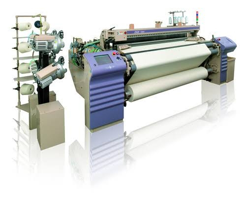
Air-jet loom have become very popular in recent years. The air-jet weaving machine was selected as one of the top innovations of the last decades by the Textile World Magazine. The number of air-jet weaving machine manufacturers has increased considerably over the past several years. Intensive research and development on air-jet machines have continued. As a result, air-jet looms are getting wider , faster and more economical than before.
Back Ground of the Invention of Air-jet weaving machine:-
U.S.Pat.No. 4686,152 illustrates a method and apparatus for grinding or buffing a metal reed of an air-jet loom by manually moving a buffer along the tunnel while the reed is positioned on the loom.
U.S.Pat.No. 4640,316 illustrates another apparatus for treating an air-jet loom reed, while on the loom wherein air measuring is manually moved in shedding motion along the top of the loom reed.
Heretofore there was no method or apparatus available which would uniformly and consistency permit measurements of air flow and at the same time provide a means to make indicated adjustments to the loom reed to meet requirements as to air flow performance. Accordingly , objects of this invention include analysis and regulations of air flow for different types of filling with reduction in air consumption of the loom.
Another object of the invention is to permit the correction of problems associated with filling insertion and to assist in speeding up the loom while providing higher quality of cloth fewer loom stops.
Summary of the invention:-
It has been found that a method and apparatus may be provided for optimising air flow characteristics of an air-jet loom by moving the reed from the loom and positioning same in the frame where a carriage is provided for rolling contact accordingly to a predetermined path for measuring the physical nature of the air tunnel to accommodate improved air flow.
Brief Description of the Drawing of air-jet weaving machine:-
The construction designed to carry out the invention will be here in after described, together with the other features there-on.
The invention will be more readily understood from a reading of the following specifications and by refrence to the accompanying drawings forming a part there-of , wherein an example of the invention is shown and wherein:-

Fig. 1 is a perspective view schematically illustrating a frame for positioning a loom reed in inverted position remote from the loom together with a driving apparatus for moving the carriage.
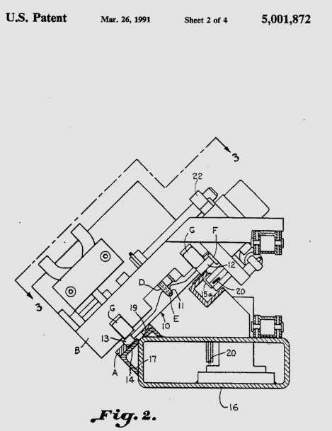
Fig. 2 is a transverse sectional elevation taken on then 2-2 in fig.1 with a carriage illustrated a being positioned upon the loom reed.

Fig.3 is a plan view of the carriages taken on the line 3-3 in Fig. 2 : and
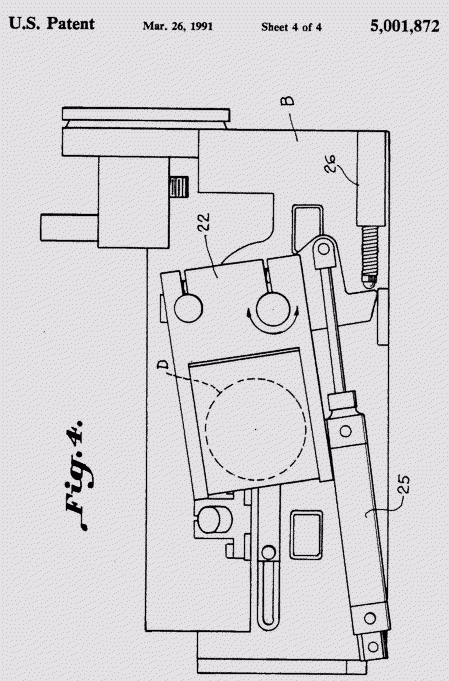
Fig. 4 is a plan view illustrating an apparatus for positioning a buffer for altering the loom reed in accordance with the invention.
Description of a Preferred Embodiment:-
The drawings illustrate a method and apparatus for enhancing air flow characteristics in an air-jet loom reed broadly designated at 10. The reed 10 has a tunnel 11 and a bottom channel 12 . The air-jet loom reed is removed from an air-jet loom. The air jet loom reed is then positioned in a mounting frame A in a fixed perforable inverted at least partially upright position. In inverted position the bottom channel 12 is at the top , with a top channel 13 on a lower guide rail 14 of the frame A. The rail 14 of the frame A is opposite and upper frame tail formed by a channel 15.
A carriage B driven by a pully C is illustrated for driving a buffing device D and an air measuring device E at a predetermined speed along the reed. The carriage illustrated as being suitably supported as by wheel F, which rolls on the bottom channel 12 of the loom reed . Thus the path of buffing device relative to the tunnel of the air-jet loom reed is located with respect to an upper portion of the reed when fixed in inverted position.
The frame A is carried by a tubular base support 16 and the tower guide rail 14 is supported by a bracket 17 while the channel 15 is carried by posts 18. A bar magnet 19 is provided to hold the reed 10 in position upon the frame A. Rolling contact of the carriage is maintained by the roller G (Fig.2) with the respective reed channel 12 and 13 . A roller 15 a is provided for positioning the carriage in respect to channel 15.
Thus Fig.1 and 2 illustrate a universal mounting frame A which can be used for all known air-jet reeds of a tunnel variety of varying lengths, heights and location of air-jet tunnel relative to top it bottom channel of the reed . The reed is held in place in the frame by the lower guide or alignment rail 14 and magnetic bar holder 19 together with the gravity effect of the weight of reed .
The drive pulley C together with a nylon coated cable 20 provide uniform or other predetermined motion to the carriage along the reed . The pulley is driven by a motor 21. It is important to note in the Drawings that the top channel 13 of the rod 10 ( as mounted in the loom ) is located along the bottom of the frame and the bottom channel 12 of the reed 10 (as mounted in the loom ) is located exposed at the top of the frame (e.g.) This is the reverse of the arrangement in the air-jet loom.
This is important because it exposes the bottom of the reed channel for exact and uniform rolling motion of the carriage along any type f reed . All types of loom reed have critical reed dimensions which are referenced from the bottom channel to the sides of the tunnel and to the bottom of the tunnel. Dimensions to and from the top channel of the reed are considerably less critical and infact can vary from one reed to another within limits without affecting the function of the reed in the weaving process.
Universal adjustment of the air measuring device E , illustrated as a pilot tube within the air-jet tunnel 11 , is provided by the monitoring which also provides universal adjustment of the buffing or grinding wheel D in and around any and all sections of the air-jet tunnel . Various types of buffing or grinding wheels designed for different buffing purpose may be utilized . Any such device or operation for altering the surface as configuration of the tunnel is referred to herein as a buffer or buffing. A universal mm mounting 23 (Fig. 3) for on jet nozzle as illustrated at 24, is provided at any desired location relative to the tunnel and at a variable distance from the pivot tube . The carriage B may be variable in width to permit extensive change of the distance of the pivot tube from the nozzle and also permit use of multiple nozzles , if this is desirable, this feature is useful because at present the location of the nozzles on the loom relative to the tunnel are fixed. This capability provides for a means to determine the optimum nozzle location for different types of filling market depending on count , denier, twist, etc.
An air-jet cylinder 25 and a potentiometer 26 are illustrated in Fig.4 connected in relationship to the buffing mechanism universal monitoring 22. The buffing mechanism having the wheel D is located by moving it in or out of the desirable position. A desired pressure of the buffing wheel may be applied to any selected part of the tunnel. Futher, by means of the potentiometer the speed of the wheel D is regulated providing for constant surfaced speed during its motion across the air-jet reed and accommodating any wear in the buffing wheel. Since the pitot tube E also has universal mounting capability both up down and in and around of the air-jet reed tunnel air flow, i. e. Pressure drop , measurement may be made in any location to the profile of the air-jet tunnel.
A nozzle 27 of a vacumme system is located in the carriage . It is moved into position automatically when the buffing is performed, and and our of way when measuring is performed. Its purpose is to clean the reed and constantly remove any particles created during the buffing process. Thus apparatus has been provided for measuring air flow for all types of air-jet reeds for all known air-jet loom.
The measuring of air flow by pressure drop from a known pressure can be performed any where in the cross section of the tunnel and at any distance from from the pitot tube to the nozzle. A variety of nozzles can be used and the nozzle location is variable relative to the tunnel and the pitot tube . The number of nozzles is also variable.
Air pressure to the nozzles can be set at variable pressure. Once air flow measurement are taken with potentially a variety of methods, the air flow can be recorded in any suitable way . Adjustments in an air flow through out the cross section of the air-jet reed tunnel and over the full length of the air-jet reed tunnel are possible variation in air flow can be produced in both cross sections and over the length of the air-jet reed to accommodate optimum filling stop arrangement, different fillings air consumption and resulting power conservation, loom speed as measured in picks per minute,and cloth quality . These adjustment are accomplished by removing or creating slightly burrs on the metal profiled dents varying the surface finish of the metal profile dent to increase or decrease air flow and to increase or decrease turbulence , varying nozzle location relative to air-jet tunnel and changing nozzle design.
While preferred embodiment of the invention has been described using specific term , such description is for illustrative purpose only , and it is to be under stood that changes and variations may be made without departing from the spirit or scope of the following claims.
Air-jet weaving machines are under constant development. Current research mainly focused on the air and yarn interlacement as well as the guide system to increase the yarn velocity and reduce the compressed air consumption.
Ref:-https://textileleaner.net.


Comments
Post a Comment